Get a quote
Apollo
  • Huasuny Will Attend ISE 2024 in FIRA Barcelona
    Nov 10, 2023 Huasuny Will Attend ISE 2024 in FIRA Barcelona
    Huasuny welcome and wait for you at Hall 4,Booth 4H240 Barcelona,Spain ISE 2024, one of the largest AV systems integration show in the world! Join us and experience the video wall solution at Hall 4, Booth 4H240 We will introduce the fourth generation flexible LED display- Travi, upgraded moving head LED display Y-Rover, and new arrival- Raptor,which can be used in multiple environments and a various of scenarios . We will be pleased to present our valuable customers and business partners the newest LED display solutions, come and visit us at ISE 2024, from 30 Jan to 2 Feb 2024 in Barcelona, Grab Via!
    View More
  • Color Gamut
    Nov 15, 2024 Color Gamut
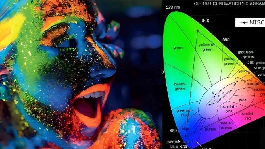
    Definition of Color Gamut Color gamut refers to the range of all colors that a device (such as a monitor, printer, etc.) can reproduce. It reflects the device's capability in color representation, and different devices have varying color gamut ranges due to differences in technology and materials. Understanding color gamut is crucial for ensuring the accuracy of colors in images and videos, especially in fields like design, photography, and printing. In the real world, the colors of the visible spectrum in nature form the largest color gamut space, which includes all the colors that the human eye can see. To intuitively express the concept of color gamut, the CIE (International Commission on Illumination) has established a method for describing color gamut: the CIE-xy chromaticity diagram. Representation of Color Gamut CIE Chromaticity Diagram The CIE (International Commission on Illumination) has developed the CIE-xy chromaticity diagram to visually represent color gamut. In this coordinate system, the range of colors that various display devices can represent is shown as a triangular area formed by connecting three points representing RGB (Red, Green, Blue). The size and shape of this area reflect the types of colors that the device can display.The larger the area, the greater the color gamut range of the device. Color Gamut Standards sRGB: The most widely used standard, suitable for most computer and web applications, covering approximately 72% of the NTSC color gamut.The sRGB color gamut was born in 1996 and has been the most commonly used standard since the CRT(Cathode Ray Tube) era until now. Almost all monitors support sRGB nowadays, and it can easily handle web browsing, graphic work, daily office tasks, and more. Therefore, achieving 100% sRGB color gamut coverage is something that many better monitors can do now. However, the sRGB color space is only about one-third of the CIE 1931 XYZ color space, and sRGB has insufficient coverage for the green part of the color gamut. So, if an image originally has very rich greens (such as a picture of green leaves), it may lack expressiveness when viewed under sRGB. More importantly, sRGB is only suitable for self-luminous display screens to display "virtual" images and cannot be used on "physical" printed materials that rely on reflected light for color display. Therefore, to standardize the colors of printed materials, the CMYK color standard came into being. Adobe RGB: Launched by Adobe, it can express a broader range of greens and cyans, making it suitable for professional photography and design.The Adobe RGB color gamut was primarily developed to address the issue that the sRGB color gamut cannot cover the CMYK color gamut used in printing systems. Its main improvement is in the display of cyan-green tones, covering approximately 50% of the CIE 1931 XYZ color space. We can see their relationship in the color gamut diagram. Adobe RGB is a considerably large color gamut, and some high-end profes...
    View More
  • Huasuny Introduces Travi Series For Rental Outdoor Applications
    Jun 21, 2023 Huasuny Introduces Travi Series For Rental Outdoor Applications
    June 20, 2023 Huasuny lauched our innovative technology Travi Series for outdoor rental applications. Travi is Huasuny's 4th generation flexible LED display, with the feature of light weight, thin,and high transparency. The Travi series will be available for multiple sizes 1250mm x 500mm, 1500mmx500mm, 2500mmx500mm etc, it has brightness of 4000nits, 3840Hz refresh rate and IP65. Pixel pitch avaliable: 6.9mm, 8.9mm, 10.4mm and 12.5mm.
    View More
  • Scan and Driving mode for LED Screen
    Oct 24, 2024 Scan and Driving mode for LED Screen
    This Article was wroten by Tony Tong, the sales manager of Huasun, and initially published in Linkedin. Scan mode, also called Scan rate or scanning driving, refers to the number of LED pixels that can be connected to a single driver IC. Each pixel is connected to a pin on the driver IC on the PCB board. The number of drivers required on a PCB board design to illuminate the pixel pitch determines the scan type. Each LED pixel is connected to one pin of the driver IC on the PCB board. The more driver ICs we have on a PCB, the lower the scan type is. Most suppliers will have 1/2, 1/4, 1/8, 1/16 and 1/32 1/48 scan types. Scan and time multiplex are the same. The scan number is the number of drivers required on a PCB board design to light up the pixel pitch: The scan design is impacted directly by: Type/performances of the drive IC; Refresh rate; Grayscale; Pixel pitch; Static scanning: Static scanning is to implement “point-to-point” control from the output of the driver IC to the pixels. Dynamic scanning: Dynamic scanning is to implement “point-to-row” control from the output of the driver IC to the pixels. Each drive IC has 16 pins and can drive 16 LED chips maximum.Static drive mode means all the LEDs on the LED Tile can driven/light up by IC at once, as shown in the following image. 1/12 scan mode, means 1/12 LEDs on the LED Tile are driven/light up by IC at one time, and next time there are another 1/12 LEDs that are driven. 1/6 scan mode, means 1/6 LEDs on the LED Tile are driven/light up by IC at one time, and next time there are other 1/6 LEDs that are driven. Brightness: The higher the resolution and the higher the brightness are,the more drivers need to be used. This means we will have less space on the PCB. The higher the scan is, the lower the brightness. Theoretically, for the same LED screen, static scanning is twice as bright as 1/2 scanning, and 1/4 scanning is twice as bright as 1/8 scanning. And 1/5 scanning is twice the power consumption of 1/10 scanning.However if brightness is not an absolute requirement, there are ways to lower the brightness by experimenting with the software. A high scan drive can reduce brightness of the LED screen and in most cases suppliers can use higher scans on higher resolution screens to compensate for brightness to be more cost effective.Because the number of required driver IC has decreased. Most high scanning Drives can be used on indoor LED screens as high performance of the screen is not an absolute requirement. Because brightness is not an issue for indoor LED screen and you won't have to compensate when there is not enough space for the PCB. Therefore, it's very important to choose a reasonable scan mode for the LED screen.It needs to be based on the brightness, power consumption, refresh rate and cost – not simply the higher the better. For Example: Taking a 1/45 scan P1.875 design with the LED and driver IC on the same side as an example: LED Tile size:300×168.75mm. pixel resolution: 160×90=1...
    View More
  • HUASUNY New Technology -Jade Series Indoor Fixed Fine Pitch LED Screen
    Jun 02, 2022 HUASUNY New Technology -Jade Series Indoor Fixed Fine Pitch LED Screen
    We are excited for our latest technology--Indoor fixed LED panel Jade Series. The indoor fixed LED display is such a display that it is immovable, fastened. And it fixed at a particular place in such a position that it cannot move on its own. These LED displays are also a great source of advertisement using indoor as well as outdoor applications Pixel pitches avaliable: 1.9mm, 2mm, 2.6mm, 3.9mm Panel sizes: 1000mm x 500mm, 750mm x 500mm, 500mmx500mm, 250mm x 500mm, sizes can be customized. Main features: light weight and easy to set up. More details coming soon...
    View More
  • LED Screen problems ONLY manufacturer knows
    Oct 22, 2024 LED Screen problems ONLY manufacturer knows
    This Article was wroten by Tony Tong, the sales manager of Huasun, and initially published in Linkedin. Problem 1: Ghosting Phenomenon This issue with scanning indoor led screens is the ghosting phenomenon, which is mainly caused by the charging and discharging of parasitic capacitance on the PCB during the operation of switching rows and columns on the display screen. This results in LEDs that should not be lit up being illuminated, especially when applied to oblique scanning, where the ghosting problem is more pronounced. Ghosting issues on LED scanning screens have both upward and downward ghosting effects. Problem 2: Colorshift at Low Grayscale The test pattern used at picture 2 consists of a low grayscale white pattern. When the pre-charging function is turned on, we can see that the module appears reddish. Picture on the right shows use of some better chipset to eliminate color shift when pre-charging has just been turned on. Problem 3: Non-uniformity at Low Grayscale Non-uniformity is particularly noticeable under low grayscale conditions, which places very strict requirements on the uniformity of driver ICs. Pre-charging is performed to raise the voltage levels in the rows to eliminate downward ghosting effects. However, this method can lead to issues of non-uniformity in certain areas. This effect is more visible to the naked eye when displayed with low grayscale images. Unevenness in medium and high grayscale images may result from differences in PCB layout and varying voltage levels due to discrepancies between driver ICs. A low grayscale monochrome test pattern was utilized in Figures 1 and 2. There will be deviation between LEDs in the same patch. The sum of such characteristic deviation is the cause of the blurry screen effect. As shown in Figure 3 and 4, the same source materials are displayed in full screen. The brightness of individual pixels differs and is distributed randomly as shown in Figure 3, and does not show significant improvement even under increased brightness. Brightness calibration is an effective way to fix the blurry screen effect. However, the cost of brightness calibration is high and recalibration will be required for aged LEDs. In other words, recalibration will be needed at regular intervals, creating higher maintenance costs. Some better IC utilizes built-in brightness equalization to create more even, smooth screen brightness as shown in Figure 4. Problem 4: Dim Line at The First Scanline The way a scan type display works is to light up LEDs line by line, You will notice that the first scan line in the upper and middle parts of the picture are abnormally dark; This phenomenon is known as the dim line.If LEDs in a frame are off for longer than they are conducting, parasitic capacitance in the PCB module will lead to increased column voltage. In particular, the column voltage when Row 1 is scanned and conducting will be higher than the column voltages when the other rows are scanned. Problem 5: Gradient Dim L...
    View More
1 2 3 4

A total of 4 pages

click here to leave a message

Leave A Message
If you are interested in our products and want to know more details,please leave a message here,we will reply you as soon as we can.

Home

Products

about

contact