In modern industries where visual information is mission-critical—such as Stage performance, traffic command, advertising media and other fields—display signal backup plays a vital role in maintaining operational continuity. Then let us explores the concept, methodologies, and emerging trends in display signal redundancy.
1. What is Display Signal Backup?
2. Key Applications
3. Consequences of Signal Interruption
4. Setting Up Redundancy Backup
5. Conclusion
① What is Display Signal Backup?
Display signal backup refers to the process of duplicating or mirroring video signals from a primary source to one or more secondary displays or systems. The goal is to ensure uninterrupted visual output in case of primary display failure, signal degradation, or source device malfunctions.
② Key Applications
1. Mission-Critical Environments
-
Hospitals: Operating rooms rely on backup displays to avoid interruptions during surgeries.
-
Aviation: Redundant cockpit displays ensure pilots receive consistent flight data.
-
Broadcast Studios: Backup feeds prevent on-air blackouts during live events.
2.Enterprise & Control Rooms
-
Stock exchanges and security centers use mirrored dashboards to maintain 24/7 monitoring.
3.Consumer Applications
-
Gaming setups and home theaters increasingly adopt redundant HDMI switches for seamless failover.
③ Consequences of Signal Interruption:
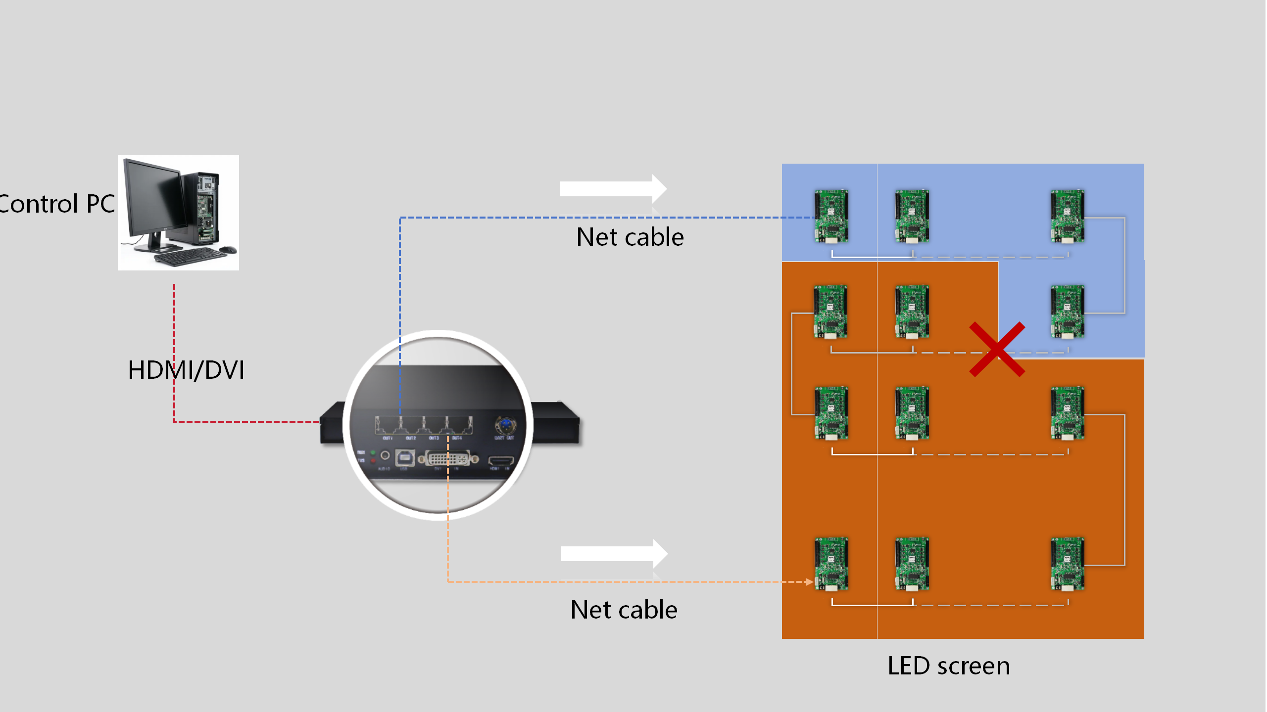
In such a scenario, signal transmission halts at the point of failure. Downstream modules beyond the break (depicted as grey-background screens in the diagram) lose connectivity, resulting in complete display failure. Meanwhile, upstream modules (green-background screens) continue functioning normally. This disruption highlights the vulnerability of linear signal chains and underscores the need for proactive redundancy solutions.
Four Strategic Benefits of Redundancy:
1.Operational Continuity
Redundancy minimizes downtime, ensuring displays remain operational during events, live broadcasts, or digital signage campaigns where interruptions could compromise audience engagement.
2.Financial Protection
For commercial applications, every minute of downtime equates to lost advertising revenue and diminished ROI. Redundancy preserves revenue streams by maintaining constant visibility.
3.Brand Integrity Preservation
Large-scale displays often serve as brand ambassadors. Unexpected failures risk damaging corporate credibility, while consistent performance reinforces professional reputation.
4.Public Safety Assurance
In transportation hubs, emergency systems, or public information displays, redundancy becomes a safety imperative. Uninterrupted operation ensures critical messaging reaches audiences during emergencies.
④ Setting Up Redundancy Backup
Now that we understand the importance of redundancy, let’s explore how to set it up effectively. We will cover three scenarios:Network port backup scheme, Sending card backup scheme, and Dual system backup scheme.
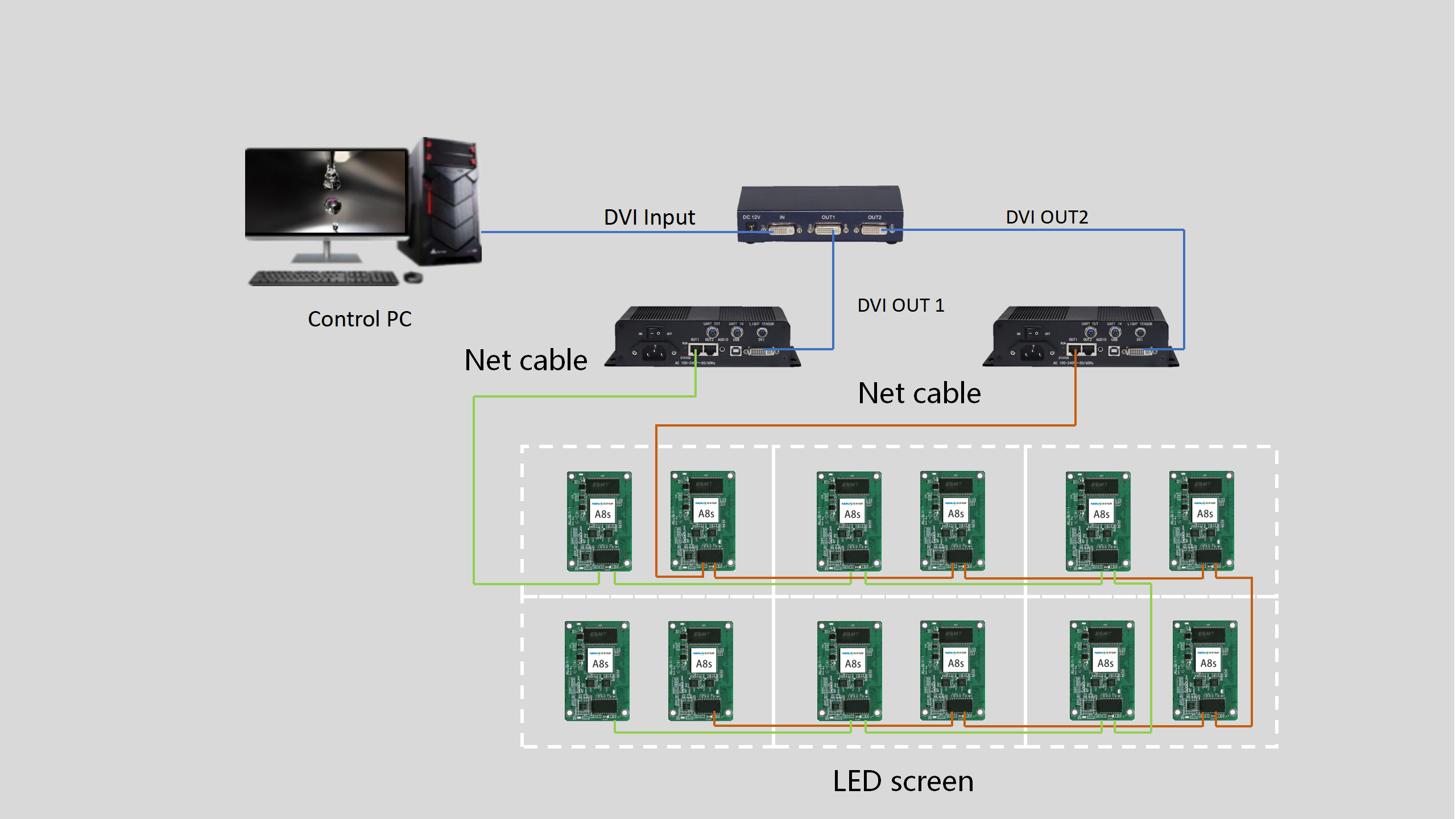
1. Network port backup scheme
-
Operation mechanism of loop backup
Software Configuration
After the hardware connection is over, next we will process the software part.
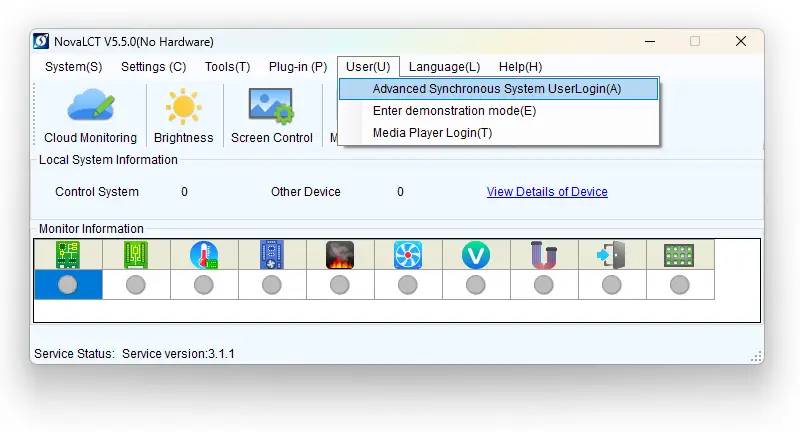
First, launch the NovaLCT software and log in by selecting “Advanced Synchronous System User Login” and then enter the password “admin“.
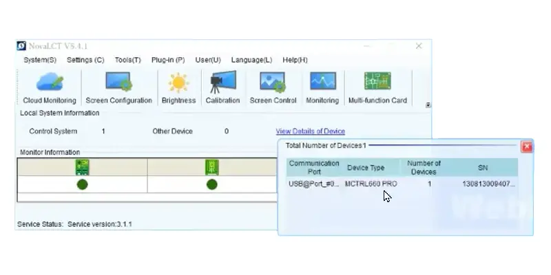
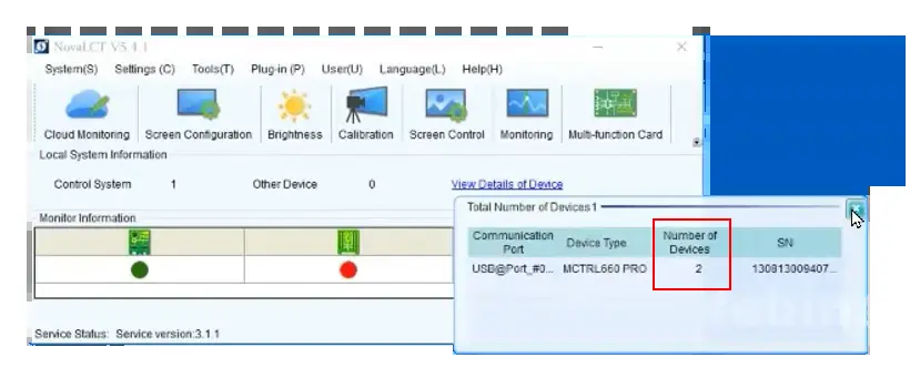
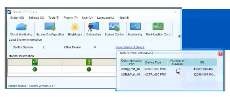
Once logged in, check the device details by clicking on “Video Details of Device“. This will provide information such as the communication port, device type, number of devices, and serial number (SN). In this example, the device type is MCTRL660 Pro, with a total of 1 device connected.
Next, click the “Screen Configuration” button. A new interface will appear, showing only one communication port; select this port and click “Next”. You will see another screen with three tabs: Sending Card, Receiving Card, and Screen Connection.
In this interface, we do all settings as normal. For detailed configuration steps, please refer to this post: NovaLCT Screen Configuration Guide.
After that, another key step we have to process: we need to set up the redundancy information in the interface of the “Sending Card”.
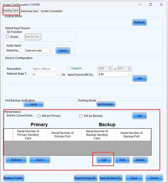
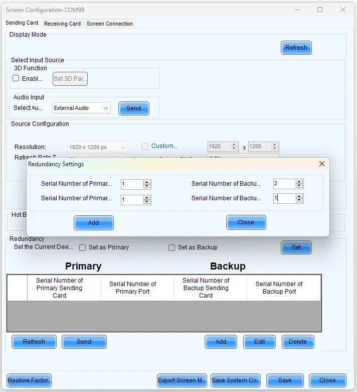
In the redundancy section, click the “Add” button. A pop-up titled “Redundancy Setting” will appear, prompting you to enter four parameters: Serial Number of the Primary Sending Card, Primary Port Serial Number, Serial Number of the Backup Sending Card, and Backup Port Serial Number.
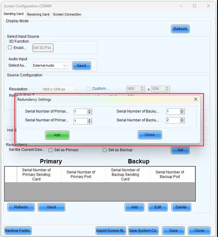
In this case, it is obvious that both the Serial Number of the Primary Sending Card and the Serial Number of the Backup Sending Card will be set to 1, as we are using only one sending card. The Primary Port Serial Number is 1, and the Backup Port Serial Number is 2 since we use Outport Port 1 as the main channel and Output Port 2 as the backup in the hardware connection.
After entering the correct values, click “Add” to save the redundancy settings. Finally, remember to click “Send” to save the information to the sending card.
To this point, all setting is over,
Test
To validate the setup, disconnect the Ethernet from the primary port and observe if the display remains unaffected. If it does, the redundancy bakup is properly configured.
2.Sending card backup scheme
Setting Up Redundancy on Cascaded Sending Cards
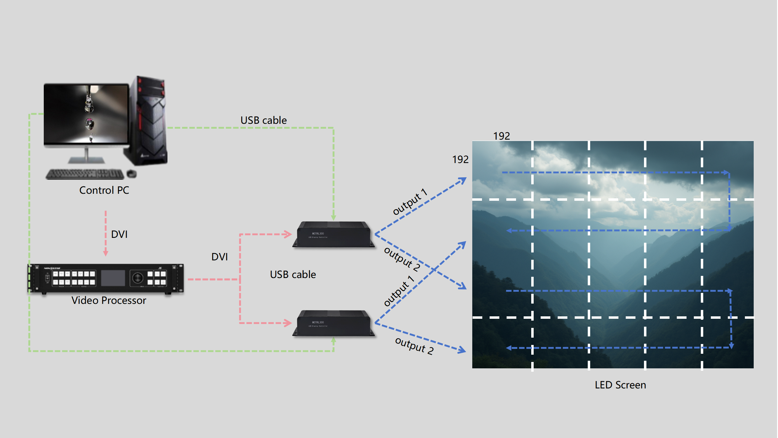
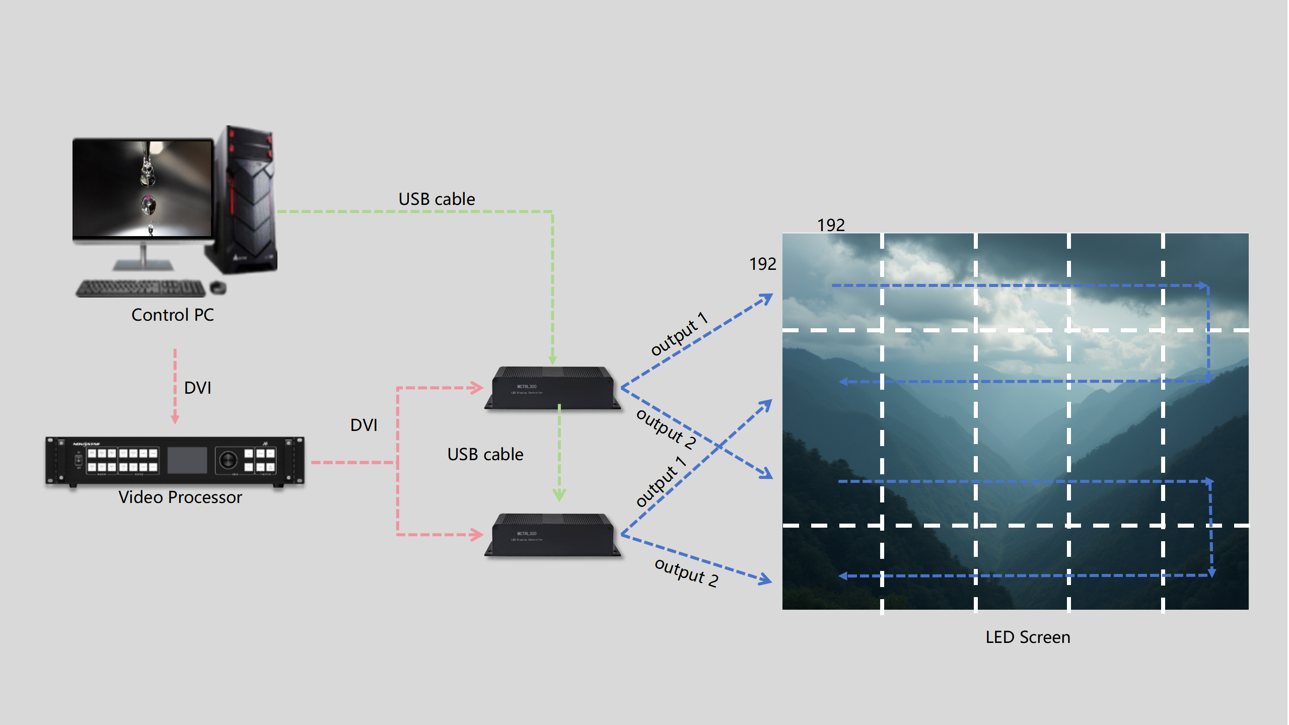
In this example, the first sending card connects to the control PC and serves as the main channel, while the second sending card cascades with the first and functions as the backup channel. Both controllers utilize output 1 to connect to the LED screen. Remember, you can use any other output you prefer; just make sure to adjust the corresponding settings in the software accordingly.
Please note that the two sending cards are cascaded using a USB cable. For more information about cascading, check this post: LED Display Cascade Connection Full Instruction.
Software Configuration
Once the hardware setup is complete, we will proceed with the software configuration.
First when we have login. Click on “View Details of Device” to check the device information. In this instance, we are using two sending card units for cascading, so you’ll see that the Number of Devices is 2.
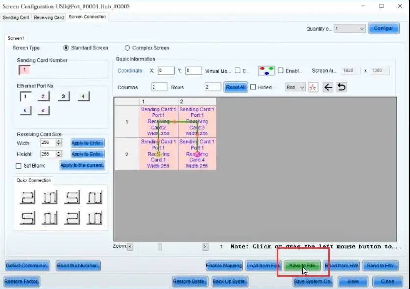
Next, navigate to the Screen Configuration main interface and then open the “Screen Connection” tab. Here, you’ll see both sending cards listed at the top left of the interface. As shown as following image, it display two Sending Card Number
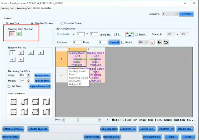
It is worth noting that since we are using the first sending card as the main channel, here we only need to configure this sending card, in other words, it is the Number 1 Sending Card. Then follow the same logical steps based on your actual LED screen setup, and also click “Save Hardware” to store the configuration.
After that, go to the “Sending Card” tab to set up the redundancy information. Click the “Add” button in the redundancy section. When the pop-up window appears, enter the same information as above mentioned. In this case, the Serial Number of the Primary sending card is 1, the Serial Number of the backup sending card is 2, and both the primary port and the backup port correspond is 1.
Also don’t forget to send the setting to the hardware. Please note, that if you adjusted the port numbers during the hardware setup, make sure to update them too.
Test
Disconnect the first sending card (main channel) and check if the screen continues to display content normally. If it works, it confirms that the backup is functioning properly; if not, we will need to check the hardware and software settings.
Setting Redundancy on Non-Cascaded Sending Cards
Unlike the last case, In this case, both sending cards connect directly to the control PC and they have no direct cable between them, in other words, they have no cascading relation.
Hardware Setup
First, let’s establish the hardware connections. As shown in the above image, this connection still involves two sending cards, but they are not linked by a USB cable. Instead, the control PC connects to each sending card with its own separate cable—one for the first sending card and another for the second.
Software Configuration
After completing the hardware setup, we will proceed with the software configuration for this setup.
Before diving into the settings, click on “View Details of Device” to check the device information. In this example, there are two separate USB communication ports, each connected to one device. This explains the presence of two ports, as the sending cards are independently connected to the control PC
Next, access the “Screen Configuration” interface where you’ll need to select which communication port to set up first. First, choose the first port to move forward. In the Screen Configuration interface, configure the “Screen Connection” with the same rules. There’s no need to revisit this process in detail, as you should be familiar with it by now.
An important step at this point is to save the “Screen Configuration” settings as a local connection file (*.src) for use with the other sending card. Be sure to save the hardware settings as well.
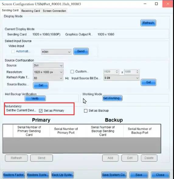
Next, navigate to the “Sending Card” tab to configure the redundancy settings. Click on “Set as Primary” and then hit “Save”. Now we have done the setting for the first sending card.
After this, close the “Screen Configuration” interface and click the button “Screen Configuration” again. Here we select the second communication port to continue, which means, we will set the second sending card.
For the “Screen Connection” settings on the second sending card, you can click “Load from File” to select the file you just saved. This will automatically load the same settings for the second sending card, saving you the effort of configuring everything manually.
Afterward, save the settings to the hardware again. Finally, go back to the “Sending Card” tab to configure the redundancy settings for the second card. Select “Set as Backup” then click “Send” .
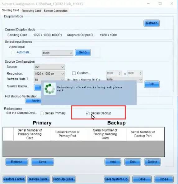
Now, all configurations for this situation are complete.
Test
Once configured, test by disconnecting the primary sending card. The LED display should continue functioning if the backup setup is successful. If not, check the settings including hardware and software.
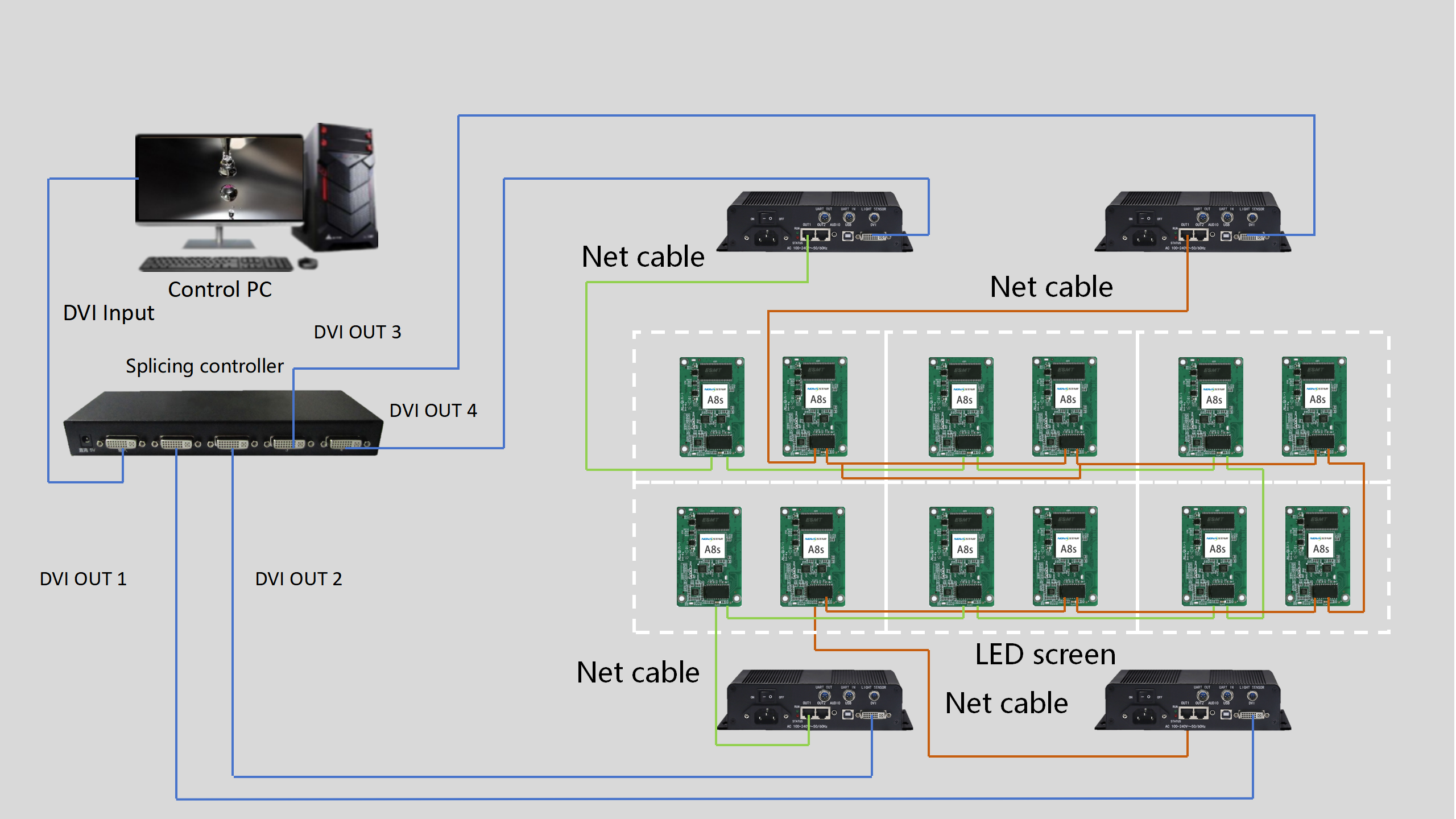
3.Dual system backup scheme
2 independently operated control systems
2 independent control systems with loop backup
⑤Conclusion
As display technologies advance, so do the risks of signal interruption. Implementing a robust backup strategy—whether through hardware duplication, network redundancy, or AI-enhanced systems—is no longer optional for industries where visual downtime equals financial loss or safety hazards. Future innovations in edge computing and quantum encryption may further redefine how we secure display signals.